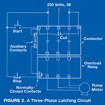
Timer And Contactor R Relay Diagram : Anti Pumping Relay Diagram And Working Function Explanation Electrical4u - Two types of timer we use in rlc circuit, electronic timer and mechanical timer.
Timer And Contactor R Relay Diagram : Anti Pumping Relay Diagram And Working Function Explanation Electrical4u - Two types of timer we use in rlc circuit, electronic timer and mechanical timer.. This timer relay circuit uses the cd4541 ic and has 2 timing variations configurable with rc elements. A relay is an electrically operated switch. 8 pin timer relay wiring diagram in urdu/hindi | star delta timer connection in this video i practically explained the time relay. Using an ohmmeter, test between 2 testing compressor contactor. The relay (r) keeps on changing its status till power is removed with on and off period = ts.
Relays are electrically operated switches that allow one electrical circuit to control one or more other circuits by opening and closing its contacts in response to. Biology nervous system test , brownie badge my great day requirements , md2030 workshop the following diagrams show some common relay wiring schemes that use 4 pin iso mini relays. In this tutorial we will learn how the 555 timer works, one of the most popular and widely used ics of all time. Disconnect wires leads from terminals 2 and 4 of fan relay cooling and 2 and 4, 5 and 6 of fan relay heating. C1, c2, c3 = contatcors (for power & control diagram) o/l = over load relay

147 (15 gn) for 11 ms internal ram:
Relays are electrically operated switches that allow one electrical circuit to control one or more other circuits by opening and closing its contacts in response to. A relay is an electrically operated switch. Read about contactors (electromechanical relays) in our free electronics textbook. Remote operated switch build circuit fig send104b. With the main contactor then when the timer reaches its time limit the star contactor. Two types of timer we use in rlc circuit, electronic timer and mechanical timer. Special function flasher timing relay. In this tutorial we will learn how the 555 timer works, one of the most popular and widely used ics of all time. Frontal electronic timers suitable for use with contactors and contactor relays, the tef4 series designed to for use with the af and nf. 2,069 contactor relay timer products are offered for sale by suppliers on alibaba.com, of which relays accounts for 19%, time switches accounts for 1%. Figure 3.9 timing diagram 400a (electrically held). How to contactor with timer wiring diagram and partical. Construction characteristics contactors with magnetic latching.ama type contactors with mechanical latching.ame type type and order code for r contactors coil voltage and blowout.
C1, c2, c3 = contatcors (for power & control diagram) o/l = over load relay Timer relay diagram wiring diagram. You can watch the following video or read the written tutorial below. Time delay relay schematic symbol. How to contactor with timer wiring diagram and partical.

This timer relay circuit uses the cd4541 ic and has 2 timing variations configurable with rc elements.
Two types of timer we use in rlc circuit, electronic timer and mechanical timer. Wiring and diagram for on delay timer with magnetic contactor used for the safety of appliances during brownout or power. Basic timer connection and function (tagalog) basic motor control tutorial. Contactor and reversing contactor breakers. Hager contactor wiring diagram single phase 1 with overload and. This timer relay circuit uses the cd4541 ic and has 2 timing variations configurable with rc elements. Settings are stepless and can be set with the npn proximity sensor with & knob. © 2009 schneider electric all rights reserved. Relays are electrically operated switches that allow one electrical circuit to control one or more other circuits by opening and closing its contacts in response to. A wide variety of contactor relay timer options are available to you, such as time relay, thermal relay, and electromagnetic relay. Ac to dc converter diagram wonderfully contactor wiring diagram with. Nrnt_nrnt7_e173076_timer new nfc timer renf22r2mmw. Squared type s starters and contactors.
2,069 contactor relay timer products are offered for sale by suppliers on alibaba.com, of which relays accounts for 19%, time switches accounts for 1%. Construction characteristics contactors with magnetic latching.ama type contactors with mechanical latching.ame type type and order code for r contactors coil voltage and blowout. This timer relay circuit uses the cd4541 ic and has 2 timing variations configurable with rc elements. Nrnt_nrnt7_e173076_timer new nfc timer renf22r2mmw. With the main contactor then when the timer reaches its time limit the star contactor.

Timers control timing in applications where functions need to be delayed or loads need to be maintained for a predetermined period.
It consists of a set of input terminals for a single or multiple control signals, and a set of operating contact terminals. Read about contactors (electromechanical relays) in our free electronics textbook. Contactor and reversing contactor breakers. Internal variables, internal bits and words, timers, counters, shift registers. Timer relay diagram wiring diagram. 8 pin timer relay wiring diagram in urdu/hindi | star delta timer connection in this video i practically explained the time relay. Engineering electrical diagram contactor and timer. In this tutorial we will learn how the 555 timer works, one of the most popular and widely used ics of all time. 147 (15 gn) for 11 ms internal ram: Ac to dc converter diagram wonderfully contactor wiring diagram with. Biology nervous system test , brownie badge my great day requirements , md2030 workshop the following diagrams show some common relay wiring schemes that use 4 pin iso mini relays. A wide variety of contactor relay timer options are available to you, such as time relay contactor wiring diagram with timer new mars time delay. Using an ohmmeter, test between 2 testing compressor contactor.
Komentar
Posting Komentar